

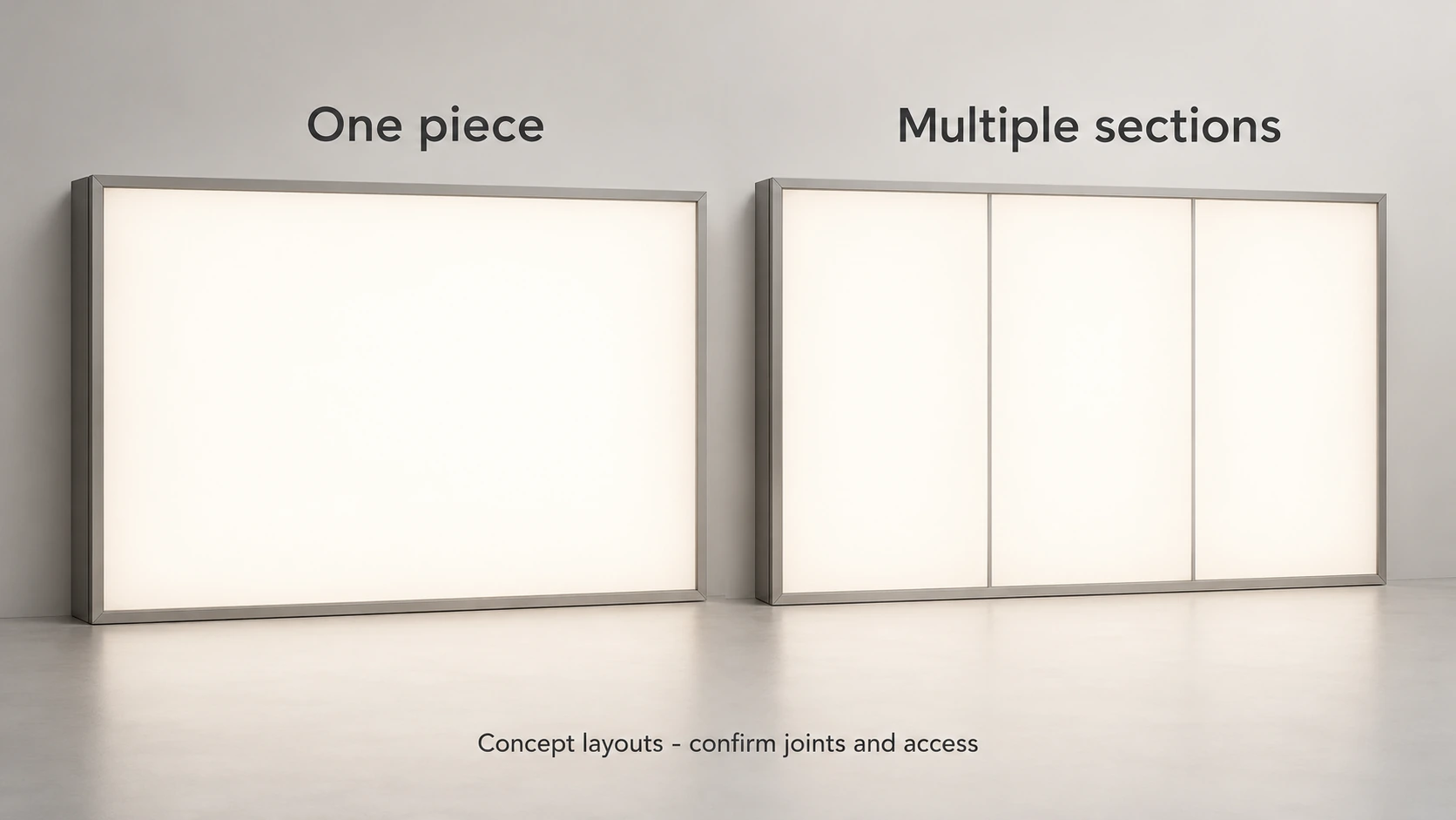
A large illuminated retail backdrop may need to appear as one continuous surface, or it may be divided naturally by cabinet uprights and display bays. Once the overall dimensions are set, the next decision is whether to supply the light guide panel as one piece or divide it into several illuminated units.
The choice needs to accommodate appearance, delivery access, installation and future replacement. A one-piece layout can reduce the number of joints between panels. A layout with multiple sections can adjust the size of each delivery unit, while adding edges, supports and joints that need coordination.
Our custom light guide panel specification guide covers the overall requirements before ordering. This article examines how to divide larger illuminated retail surfaces, helping designers, shopfitting teams and buyers compare one-piece and multi-panel proposals.
1. Mark the Areas That Need Continuous Illumination
Before discussing one piece or multiple sections, mark the illuminated areas customers will actually see on the elevation drawing. Is the intended appearance a complete backdrop, or separate illuminated surfaces within individual bays? Which areas will be covered by uprights, shelves, signage or facing materials? Which edges are visible from the front, from the side and as customers move along the aisle?
If the cabinet already contains separate display bays, start by comparing a layout divided along those boundaries. If the design calls for a continuous backdrop, identify where structural edges or visual divisions are acceptable, then discuss the corresponding panel layout.
Show the outer panel dimensions, effective illuminated area and dimensions of the facing material or graphic separately. They serve different purposes and should each be defined on the drawing.
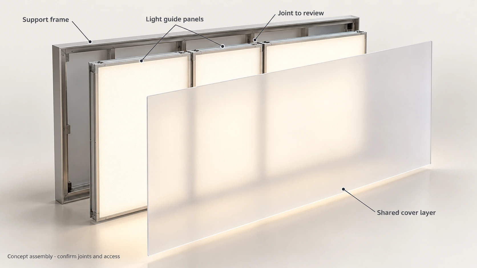
A single sheet of facing material may cover several light guide panels. Conversely, one complete light guide panel may sit behind a graphic or structure divided into sections. Draw the two layers separately so that the team can discuss where joints will occur and whether they affect the visible result.
2. Check the Complete Handling Route Using the Delivery Units
Ask the supplier for the proposed delivery units' outer dimensions, packaged dimensions and weight, then compare them with the site route. Review the journey from the unloading point to the final installation position, including the goods lift, door openings, corridors, turns and working space at the installation area.
Door width and height are part of that review. A long panel passing around a corner also needs space to turn. Once it reaches the installation area, confirm whether it can be moved into the required orientation and whether the handling team and equipment have room to operate. Include the proposed unpacking location in the delivery plan.
For a multi-panel proposal, check each section against the route. Equal divisions on the finished elevation may not suit the handling conditions. Adjust the layout with the access route, cabinet bays and proposed installation sequence in view.
Record the construction sequence too. Will the panel be placed before the cabinet sides are closed, or installed from the front after the cabinet is complete? If the first installation relies on an opening that will later be closed, confirm a separate route for future replacement.
3. Draw Joints, Supports and Removal Directions Together
Compare possible division lines with cabinet uprights, display bay boundaries and decorative lines that can remain visible. Use a section drawing to examine those locations: how the panel edges are treated, where supports sit, how facing materials cover the assembly and what can be seen from the side.
A joint also needs assessment with the light operating. When adjacent panels are illuminated, check the connection area for bright bands, dark lines or differences in light color. Where a diffuser or display graphic sits in front, review it using the proposed materials and positions between layers to confirm the final visible effect.
Coordinate the fixing structure with each unit. Establish how each panel is supported, whether fixing parts obscure the illuminated area and which neighboring components must move when one panel is removed. Where the structure uses acrylic, the fixing detail should also accommodate dimensional changes with temperature. ACRYLITE's acrylic sign fabrication guide addresses expansion allowances, support and service access as design considerations. Confirm the actual allowances for the project's materials and construction.
Specify panel division and independent replacement separately. If all panels sit behind a shared facing layer or fixing frame, replacing one may first require removal of those covering parts. Mark the removal direction, necessary opening, access to connections and route out of the assembly. Review them against the space available after the store fit-out is complete.
4. Compare One-Piece and Multi-Panel Proposals in the Same Table
Base both proposals on the same elevation, viewing task and facing material. This makes the conditions each proposal needs to resolve easier to compare.
| Comparison item | What to check in a one-piece proposal | What to check in a multi-panel proposal |
|---|---|---|
| Visible illuminated surface | Effective illuminated area, perimeter edges and overall appearance | Joint positions, appearance of adjacent panels and the result behind the facing material |
| Delivery and site access | Whether the complete delivery unit can follow the route and reach its installation orientation | Whether every section suits the route and whether there is space for assembly |
| Support and fixing | Support for the complete unit, fixing details and visible edge treatment | Support for each section, alignment between panels and joint details |
| Replacement route | Whether the complete panel can be removed through the finished cabinet and access route | Which covering parts and neighboring panels are involved in removing one section |
| Samples and delivery review | Representative details and conditions to confirm at the final size | Adjacent panels illuminated together, assembly positions and unit identification |
Consider a hypothetical fragrance display backdrop divided into several cabinet bays. Customers view it from the front and approach it along the aisle. Prepare a one-piece backdrop layout, then a second layout divided along the bay boundaries.
For the one-piece proposal, establish the route for bringing in and removing the complete unit. For the multi-panel proposal, check whether the uprights can cover the proposed joint details and assess the illuminated appearance from the side. If both meet the access requirements, compare the sample appearance and replacement process before choosing.
With merchandise in place, review the relationship between the background, bottles, liquid and labels. The perfume display lighting guide provides a method for that review.
5. Assess Joints with Adjacent Panels and the Intended Facing Materials
A sample for a multi-panel proposal should include the adjacent panels and connection details under review, together with the proposed supports, edge treatment and facing material. Illuminating panels separately helps assess each one. Illuminating them together in the intended detail allows the team to review their relationship.
Follow the customer viewing route and record the appearance from the front, from the side and when approaching merchandise. Review again with the ambient lighting operating and confirm the conditions specified for use. Where dimming or light color changes are required, compare the states selected for acceptance.
If a bright or dark line appears, mark its position and assess its relationship to panel edges, support obstruction, facing materials or assembly positions. See the light guide panel bright edge, dark zone and LED dot inspection guide for further investigation. For proposals behind signage or display graphics, use the retail backlighting checklist to review the final displayed result.
A representative detail sample can support approval of the joint proposal. Retain the corresponding checks for overall illumination, support and handling at the final size. Record the accepted sample, drawing revision, materials, panel positions and viewing conditions as the shared reference for production and installation.
6. Send SEEPOSH Both Layouts and Their Constraints
When discussing large light guide panels, start with sketches of the one-piece and multi-panel layouts, accompanied by the following information:
| Information | What to describe |
|---|---|
| Elevation and section drawings | Overall dimensions, effective illuminated area, cabinet divisions, supports and facing materials |
| Joint and visible edge requirements | Acceptable division lines, areas requiring continuity and main viewing directions |
| Handling route record | Goods lift, door openings, turns, installation area and proposed delivery sequence |
| Replacement plan | Openings after fit-out, removal direction, covering parts and the route out |
| Appearance and use requirements | Facing materials, merchandise, light color, ambient lighting and operating states to assess |
| Sample review requirements | Details to sample first and conditions to confirm separately at the final size |
Through SEEPOSH's customization process, the team can discuss panel layouts, appearance requirements and site conditions together. Confirm the available single-panel dimensions, joint details and final illuminated effect for the specific proposal.
If you are designing a larger illuminated backdrop, display shelf or brand presentation surface, send drawings and access route information through the contact page. Mark the joints and replacement locations that matter most so the team can identify the parts to review first.
Frequently Asked Questions
Is a one-piece light guide panel always more uniform than a multi-panel layout?
Panel count alone does not determine the illuminated result. A one-piece proposal needs a review of the complete emitting area and edges. A multi-panel proposal also needs assessment of its joints and adjacent panels. Compare them under the agreed construction, material and viewing conditions.
Can a multi-panel layout have invisible joints?
Define the viewing positions, distances and operating states first, then assess the actual details and facing materials. Materials in front can change how visible a joint is, so a layout drawing alone cannot establish the result.
Are smaller panel sections always better?
Smaller sections adjust the size of individual delivery units while increasing the number of panels, edges and assembly details. Choose divisions to meet handling, cabinet structure, appearance and replacement needs together.
Can we order one piece and decide how to split it on site?
Define the delivery units during drawing and production planning, together with cutouts, edges and connection requirements. Obtain instructions for the specific proposal before deciding whether a finished panel can be modified on site and which parts that work would involve.


